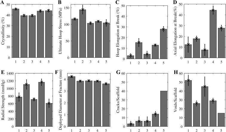
Fig. S2.
Mechanical properties of expanded tubes (A–D) and deployed scaffolds (E–H) for groups given in Table S1. Apparent crystallinity (A) inferred from DSC thermograms (n = 15). Ultimate stress at fracture (B) and the elongation at break (C) for notched dog bone specimens laser-cut with long axis of the dog bone oriented along the hoop direction of the expanded tube (n = 15). Elongation at break (D) for notched dog bone specimens laser-cut with long axis of the dog bone oriented along the axial direction of the expanded tube (n = 15). Crimped scaffolds made from expanded tubes using identical laser-cutting and crimping conditions were tested to failure upon deployment. The radial strength (E) of scaffolds deployed to 3.5-mm diameter (n = 5) is measured under a compressive radial load that is increased until fracture occurs (MSI RX650 Radial Force Testing Instrument). Scaffolds were deliberately overdilated to evaluate the deployed diameter at fracture (F, n = 5). For specimens that survive to a deployed diameter greater than that of the expanded tube (3.5 mm), the number of cracks (G) and diamond-shaped voids (H) are presented (n = 5, except for group 5, for which only one scaffold survived to 3.5-mm diameter, so 40 represents a lower bound on cracks/scaffold). In addition to coauthors M.B.K. and J.P.O., the following Abbott technologists contributed to these experiments: Thierry Glauser, Vincent Gueriguian, Bethany Steichen, Manish Gada, and Lothar Kleiner. Figure adapted from ref. 43.

