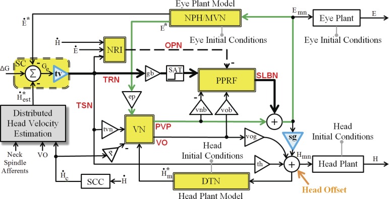
Fig. 3.
Schematic of the SMF model implemented in MATLAB/Simulink, incorporating all anatomical loops in Fig. 2 (e.g., the classical VOR in green). Each double-lined yellow block represents both the named site and its local cerebellar projections. Two blue triangles are nonlinear gain fields discussed in methods. The “head offset” (bottom right) represents an additional input to the head system used only when spatial gaze and head goals are presented concurrently; this offset is 0 in default gaze shifts. Separate head goals do not change parameters in the rest of the circuit (see parameters in Table 2). See glossary for definitions.

