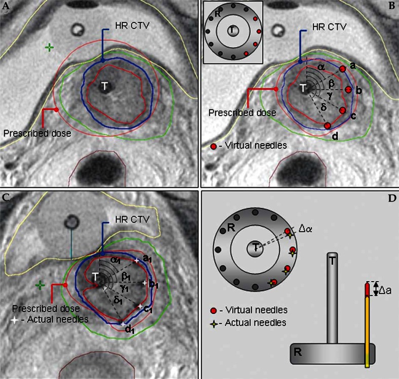
Fig. 3.
T2-weighted pelvic MRI in para-transverse (perpendicular to cervical canal) orientation with the applicator in place at time of pre-planning and actual brachytherapy. Schematic representation of the principal steps of the pre-planning process. (A) Pre-planning MRI, acquired after insertion of the intracavitary tandem/ring applicator in para-cervical regional anaesthesia. Isodose distribution of a standard intracavitary treatment plan with dose prescription at point A has been superimposed to the MRI. There is an adequate coverage of the HR CTV with the prescribed isodose. However, the prescribed isodose extends to the bladder, exceeding our departmental dose constraints for this organ. Reducing the tandem dwell-weight in order to spare the posterior bladder wall would compromise the coverage of the left part of the HR CTV due to unfavorable topography between the applicator and the patho-anatomical structures. (B) Virtual optimized intracavitary/interstitial pre-plan. After reducing the tandem dwell weight, four virtual interstitial needles were placed at optimal positions within the target volume, respecting the degrees of freedom, offered by the ring cap template (see insert in the Figure). Treatment plan optimization, utilizing needle dwell positions in addition to the intracavitary component, resulted in a pre-plan with a conformal dose distribution. The prescribed isodose conformably encompasses the HR CTV while the dose constraints for the bladder are respected. Individual needle insertion coordinates are defined on para-transverse MRI for a given ring diameter as the angle between the antero-posterior patient axis and the line, connecting the center of the tandem and the needle. (C) Planning MRI, acquired at time of actual brachytherapy, following insertion of a combined intracavitary/interstitial applicator. The pre-planned geometry has been respected during actual application. In addition to the intracavitary tandem/ring applicator, four interstitial plastic needles were inserted through the ring template, aiming at the accurate reproduction of the pre-planned insertion coordinates and depths. Actual needle insertion coordinates and depths were recorded. Treatment plan optimization, utilizing both the intracavitary and the interstitial component, resulted in a constructive actual dose distribution, comparable to the pre-planned situation. (D) Schematic representation of assessment of the geometric deviations between the pre-planned and actual implant. For each needle, the difference between the pre-planned and actual needle insertion coordinates and depth was calculated. In the example on the Figure, the deviations for anterior-most needle (needle a) are depicted
T – uterine tandem, R – vaginal ring, α, β, γ, δ – radial angles, defining virtual needle insertion coordinates at pre-planning, α1, β1, γ1, δ1 – radial angles defining actual needle insertion coordinates at time of brachytherapy, a, b, c, d – virtual needles at pre-planning, a1, b1, c1, d1 – actual needles at brachytherapy, Δα – difference between the pre-planned and actual angle of needle insertion position, Δα – difference between the pre-planned and actual needle insertion depth

