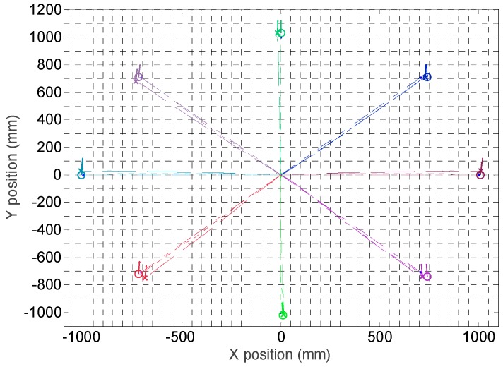
Figure 25.
Trajectories followed by the mobile robot in eight displacements. The circle depicts the final position and orientation of the mobile robot obtained with the SLAM procedure. The cross depicts the final position and orientation of the mobile robot according the information of the encoders and the kinematic model.

