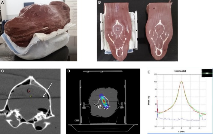
Figure 2.

Quality assurance testing, and example contouring and treatment isodose distribution. (A) Tissue equivalent plastic quality assurance phantom. (B) Phantom is cut in half dorsally, revealing the embedded skull. Radiosensitive film is sandwiched between the 2 halves for testing. (C) Axial CT image demonstrating bore for ion chamber (red dot), plan isocenter (green dot), and plane where the phantom is cut in half for film placement for quality assurance (white arrow). (D) Example of a radiation plan transferred to the phantom system, with the same isodose cloud lines as seen in Fig 1. (E) Graph comparing x‐ray–sensitive film dose profile from phantom quality assurance testing to the planned dose. The dose profiles overlap very closely.
