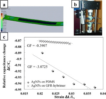
Figure 3.

(a) Tensile-simulated deformation result which shows uniform distribution of stress over the strain sensor. For tensile stress, the left end is fixed and ∼1 mN of tensile load is applied to the right end. (b) Conventional tensile tester with the strain sensor sample loaded. (c) Relative capacitance versus tensile strain for flexible strain sensors fabricated on PDMS and GFR-hybrimer substrates.
