Figure 4.

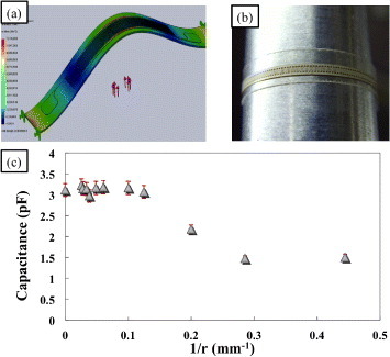
(a) Bending-simulated deformation result which shows uniform distribution of stress over the area where the strain sensor bends. Both ends are fixed and ∼ 1 mN is applied in the middle of the sensor from below. (b) Image of the flexible strain sensor wrapping around a cylinder for measurement of change in capacitance according to curvature. (c) Change in capacitance of the flexible strain sensor with curvature.
