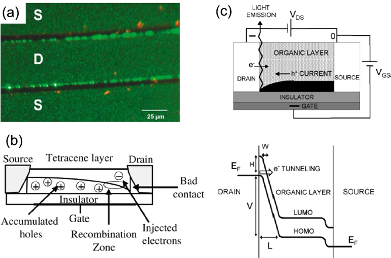
Figure 3.
(a) Optical image of electroluminescence. (b) Schematic view of carrier processes, including hole accumulation, electron injection, and electron–hole recombination in the tetracene-based LE-OFET. Reprinted from [22] with permission; © 2003, American Physical Society. (c) Working principle of an LE-FET device. The main electronic process takes place when the device is operated in standard p-type mode. Energy-level diagram shows the mechanism of electron injection from the drain electrode into the organic layer. Reprinted from [26] with permission; © 2004, Elsevier.

