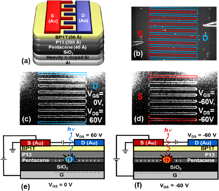
Figure 6.
(a) Schematic view of the pentacene/P13/BP1T-based LE-OFET device. (b) Photograph of device, on which the red and blue lines indicate the source and drain electrodes, respectively. CCD images show light emission from around (c) drain (Vg = 0, Vds = 60 V) and (d) source electrodes (Vg = −60 V, Vds = −60 V). (e), (f) Carrier recombination mechanisms at respective bias voltages. Reprinted from [51] with permission; © 2013, American Chemical Society.

