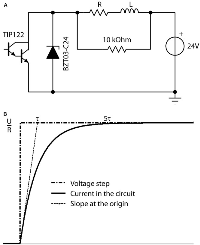
FIGURE 4.

(A) Schematic overview of the electronic circuit used to produce the desired current in the coil (L). The microcontroller produces a squared waveform, which triggers the darlington transistor (TIP122) on and off to permit the 24 V power source to drive current through the RL circuit at the desired frequency during the desired period. The zener diode (BZT03-C24) is unidirectional and thus not involved in the active circuit. However, when the transistor is off, it is the energy stored in the coil L, which drives current through the R-BZT03 diode circuit. Thus when the transistor opens, the unidirectional BZT03-C24 diode is the primary limiter of the current level induced by the coils energy to control the fall time. (B) Definition of the characteristic time Tau (τ). Current intensity inside the circuit in response to increasing voltage steps reaches more than 99.9% of its maximum (i.e., trise) after a time of ∼5τ.
