
Figure 1. Overview of the set up and functionality of the microfluidic migration device.
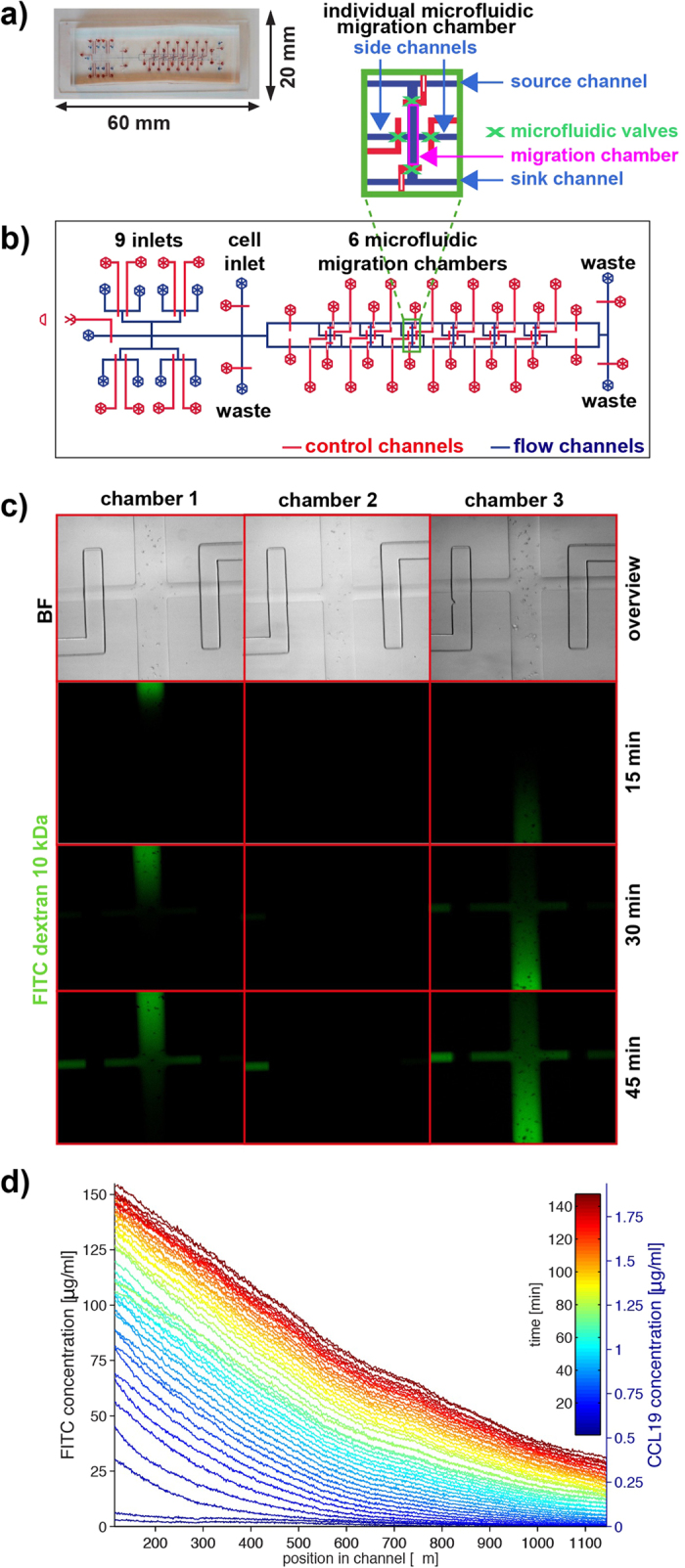
(a) Photograph of the device with flow channels filled with blue liquid and control channels filled with red liquid. (b) Schematic overview of the geometry of the entire device and an individual migration chamber (inset). Flow channels are shown in blue, and control channels are shown in red. (c) Overview of three migration chambers loaded with bone marrow derived dendritic cells (upper row) and dynamics of formation of opposing diffusion-based gradients visualized with FITC-dextran (10 kDa) in chambers one and three. In chamber two, cell culture medium is exchanged as a control. (d) Diffusion profiles averaged over the centered longitudinal section of the chamber as a function of the location in the chamber for different times up to 150 min, with the intensity mapped to the concentration of FITC dextran (10 kDa) (left axis) and CCL19 (right axis). Time is colour-coded from blue (short times) to red (long times), with each line separated by 3.5 min.