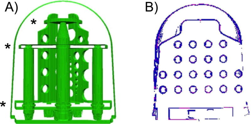
Figure 2.

A) View of the components in the CAD model on the diffusion phantom unit with the three structural plates used for tube alignment noted with (*). B) Segmentation of holes in the grid using the center slice of the image set. This shows the high gradient/intensity pixels before each cluster is filled.
