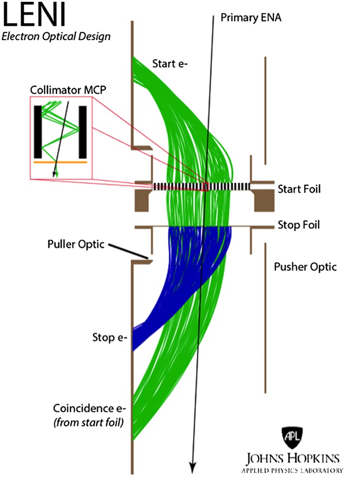
Figure 5.

The electron optics design of LENI is optimized for high angular and energy resolution imaging. The figure shows a SIMION 2‐D simulation of trajectories through the LENI instrument. Black shows the path of the primary ENA through the collimator and start and stop foils. The green shows the start and coincidence electrons derived from the back and front of the start foil, respectively. The blue shows the paths of the stop electrons produced on the stop foil. The inset shows how the collimator MCP doubles as an electron multiplier producing a large start signal.
