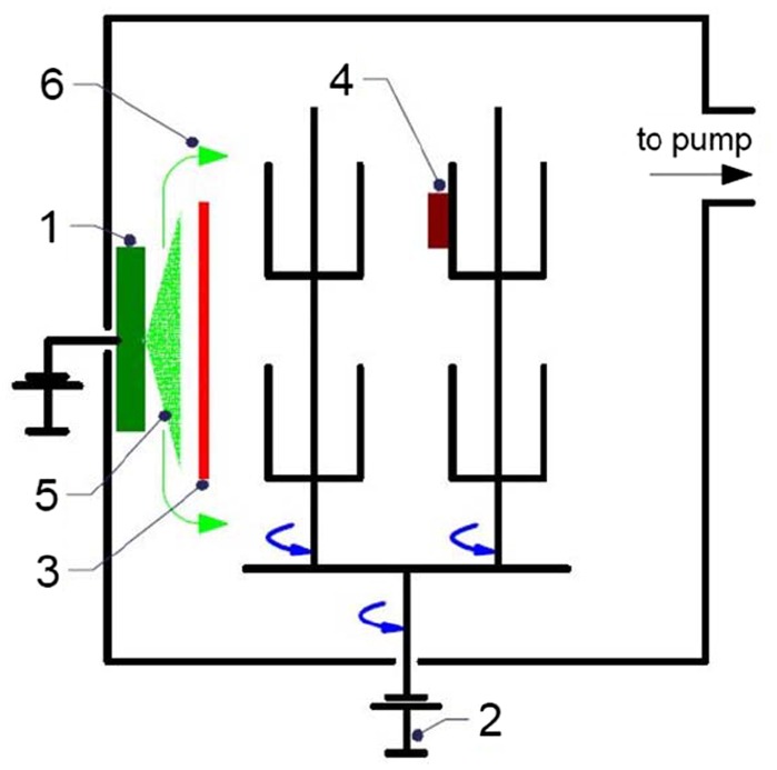
Figure 1.
Schematics of the experimental set-up for the MIE in the deposition system. The picture shows: the cathode of Cr (1), the DC bias supply connected to the twofold rotating sample holder (2), the shutter to filter the macroparticles (3), the samples of Si subject to a twofold rotation (4), the metal vapour produced from the cathode (5) and the filtered metal vapour (6). The shutter (3) is fixed during F-MIE and removed for NF-MIE.

