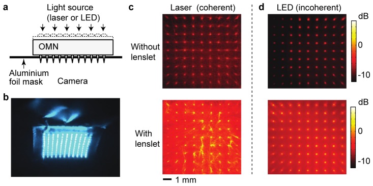
Fig. 3.
Light transmission through an assembled OMNA. (a) A setup to align the microlens array and microneedles. Aluminium foil is used to block the beams transmitted outside the needles. (b) A transmission pattern of blue laser light (491 nm) through an optimally aligned OMNA. (Visualization 1 (3.9MB, AVI) : Optimization of alignment) (c-d) Optical images of collimated 491-nm laser light transmitted through a microneedle array without a microlens array (c) and through a lens-assisted OMNA (d). (e-f) Optical transmission images of white LED light through the microneedle array alone (e) and through the lens-assisted OMNA (f). The total amount of transmission was 11%, 43%, 7.7%, and 25% in (c), (d), (e), and (f) respectively. Color bar represents light intensity normalized to the incident light. Color bar represents the optical intensity in a log scale normalized to the input.

