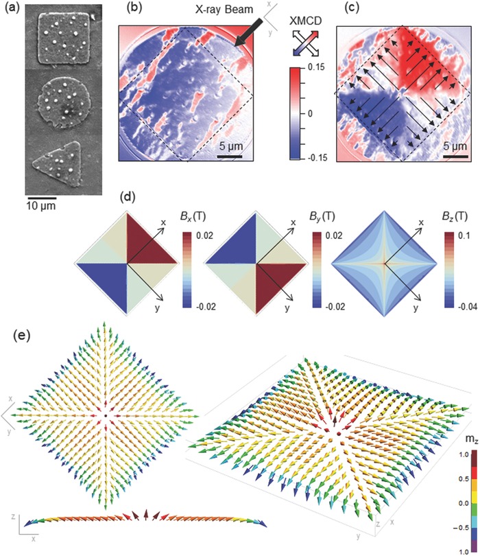
Figure 1.

a) Scanning Electron Microscopy (SEM) image of SC‐FM hybrid structures with different SC dot geometry (square, disk, and triangle). b,c) XMCD images obtained at 45 K after zero field cooling (b) and at remanence after maximum applied field of +30 mT c) for a Py layer on top of a square SC dot. Dashed lines show the limits of the SC structure. The arrow in (b) shows the X‐ray beam direction and arrows in (c) indicate the direction of the magnetization in the Py layer. d) Simulation of the Cartesian components of the trapped field distribution in a saturated squared SC dot. e) 3D Py spin texture in the squared hybrid structure determined from micromagnetic simulations. Color scale shows the out‐of‐plane magnetization component.
