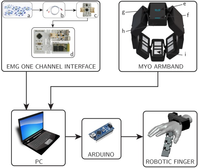
Figure 3.

Block diagram of complete system. On top left, the block diagram of EMG one channel interface is shown, where (a) surface electrodes, (b) snap leads, (c) acquisition board, and (d) control board. On top, right, the myoarm band with its major components (e) logo LED, (f) status LED, (g) expandable flex, (h) micro USB charging port, and (i) electrical sensor.
