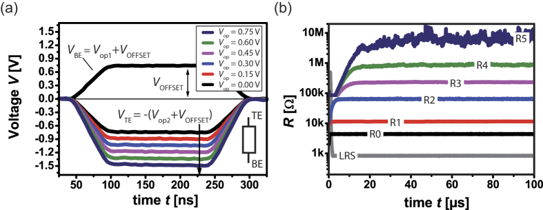
Figure 3. Basic logic functionality.
(a) The logic operands p and q are applied to top (TE) and bottom (BE) electrode, respectively. An OFFSET voltage VOFFSET is used to enable an equal stepping of operand voltages. In this example, Vop1 = 0 V holds while Vop2 is varied from 0 V to 0.75 V. (b) Depending on the pulse height, R0…R5 are written to the device. Here, a read-out voltage of 0.1 V was used to show the actual resistive states.

