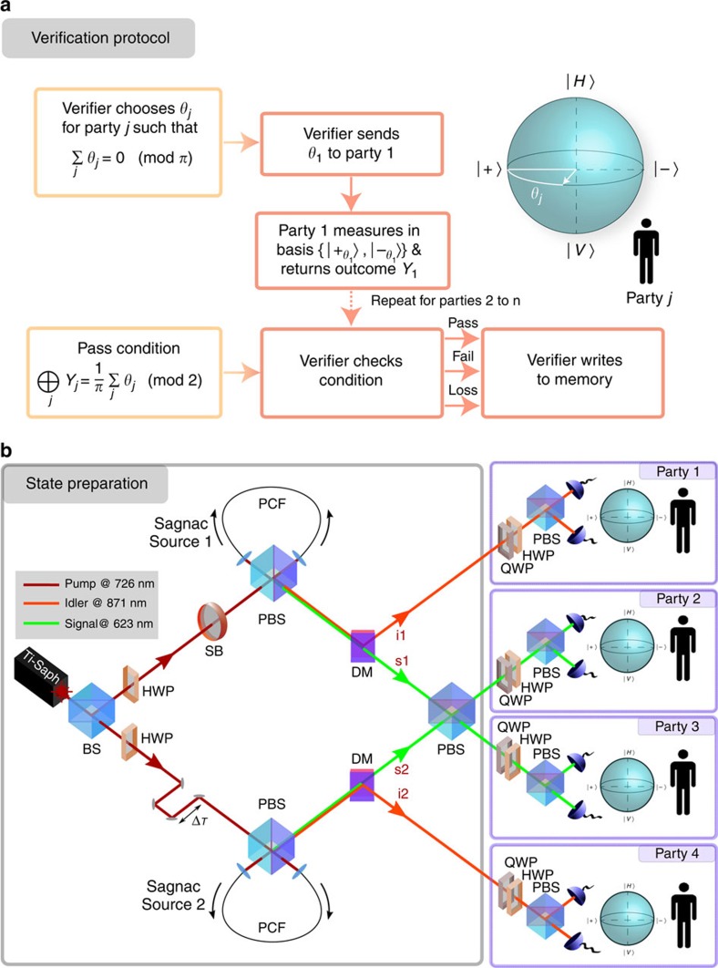
Figure 1. The verification protocol and experimental setup.
(a) A flow diagram showing the steps of the verification protocol. (b) The experimental setup for state preparation, consisting of a femto-second laser (Spectra-Physics Tsunami) filtered to give 1.7 nm bandwidth pulses at 726 nm. The laser beam is split by a beamsplitter into two modes with the polarization set to diagonal by half-wave plates. One mode undergoes a temporal offset, ΔT, using a translation stage and the other a phase rotation using a Soleil–Babinet compensator. The modes each enter a PCF source via a PBS in a Sagnac configuration, enabling pumping in both directions. The sources generate non-degenerate entangled signal and idler photon pairs by spontaneous four-wave mixing. Temperature tuning in one of the sources is used to match the spectra of the resulting signal photons in the other source. The entangled photon pairs exit the sources via the PBS and due to their non-degenerate wavelengths they are separated by dichroic mirrors and filtered with Δλs=40 nm at λs=623 nm (tunable Δλi=2 nm at λi=871 nm) in the signal (idler) to remove any remaining light from the pump laser. The signal photons from each pair interfere at a PBS and all photons are collected into single-mode fibres. Pairs of automated half- and quarter-wave plates on each of the four output modes from the fibres allow arbitrary rotations to be made before the modes are split by PBSs and the light is detected by eight silicon avalanche photodiode detectors. The protocol's software (outlined in panel (a)) is linked to an eight-channel coincidence counting box (Qumet MT-30A) and the automated wave plates to set each unique measurement basis for the parties and detect single-shot four-fold coincidences.

