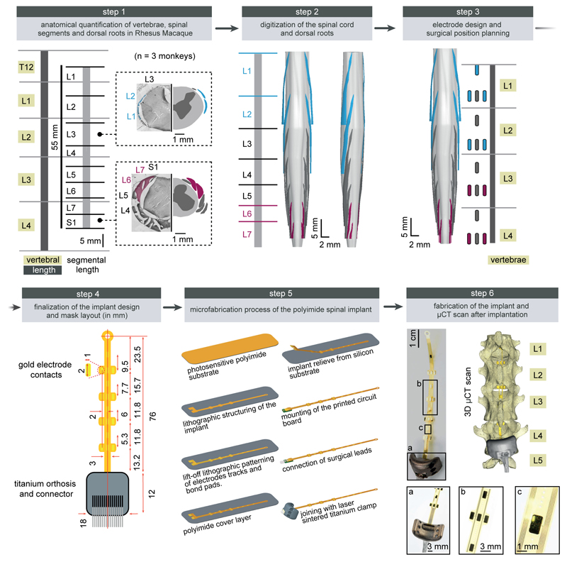
Extended Data Figure 1. Design and fabrication of the spatially selective spinal implant.
Step 1: Quantification of the length of vertebra T12 to L4, and of spinal segments L1 to S1. The photographs show coronal sections of the the left halves of the L3 and S1 spinal segments, including the dura mater, dorsal roots and spinal tissue. The complementary views show camera Lucida reconstructions of the dorsal roots, white and grey matter. The dorsal roots projecting to L1/L2 and L6/L7 spinal segments are color-coded to visualize their respective location. Step 2: 3D reconstruction of the entire lumbosacral spinal cord and dorsal roots. The dorsal roots innervating spinal segments containing the targeted extension (L6, L7) and flexion (L1, L2) hotspots are color-coded to help visualize their respective spatial trajectory. The 3D reconstructions are displayed from a dorsal view, and from a view that is rotated by 45 deg leftward around the rostrocaudal axis in order to visualize the trajectory of the dorsal roots along spinal segments. Step 3: Design of the spatially selective spinal implants, including the location of the electrodes with respect to the dorsal roots, and positioning of the implants with respect to the vertebra. The cyan and magenta shapes highlight the electrodes targeting the flexor and extensor hotspots, respectively. Step 4: Mask layout of the spatially selective epidural spinal implant. Step 5: Fabrication of the spinal implants. Processing starts with deposition of a 40 µm thick Polyimide film by spin coating on the silicon substrate. The Polyimide-based bottom layer constituting the footprint of the implant is realized through ultra-violet lithography. A 200 nm thick gold layer is deposited using vacuum evaporation and lithographically structured to create a conductive seed pattern. An additional gold layer is electroplated to a height of approximately 6 µm to create the electrodes and interconnects. A 20 µm cover layer of photosensitive Polyimide is then applied by spin coating to uniformly cover the bottom and electrode structure. A final ultra-violet lithography is applied to structure the top layer of the implant, and to create openings over the electrodes and contact pads. The implants are gently released from the carrier wafer. To create a connector, the contact pads located at the extremity of the implant are glued to a small support plate made of medical grade poly-methyl methacrylate (PMMA) sheet material. Precision milled alignment structures allow fine adjustment of the support plate to the spinal implant, and to the extremity of the leads. The support plate contained a seat in which a tiny printed circuit board with conductive stripes is fixed. Stainless steel leads with silicone rubber insulation are directly soldered to the contact pads of the implant via the contact stripes located on the printed circuit board. The resulting implants and connective leads were highly reliable mechanically and electrically. A fixation structure was realized by using 3D laser sintering of medical grade titanium. Step 6: Photographs, including zoomed insets, showing a fabricated spinal implant and a micro-computed tomography scan performed after implantation.

