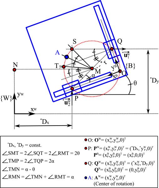
Fig. 2.
Schematic of the geometric relations and the coordinate system of the stage (scaled drawing). {W}, {B}, and is the world frame (fixed frame), the body frame (moving frame), and the input velocity vector of linear actuators in xW and yW direction, respectively. The parameters denoted by * represent the known values due to the structure or measurements.

