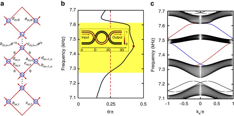
Figure 2. Projected band structure for acoustic AFI.
(a) The equivalent Chalker–Coddington network model of the coupled ring lattice that is periodic in the x direction and finite in the y direction with N unit cells. Red arrows refer to the links, viz. quarter lattice rings, and blue circles refer to the nodes, viz. coupling rings. (b) The coupling strength θ between neighbouring lattice rings as the frequency varies from 7.1 to 7.7 kHz. The yellow region covers the frequency range of strong coupling for θ>π/4. The inset shows the simulated sound pressure amplitude distribution in the U-Ring-U shape waveguide as θ reaches maximum θ≈0.43π at 7.46 kHz. (c) Projected band structure of the semi-infinite ring lattice (N=20) for pseudo-spin-up Bloch modes. The red and blue bands denote non-trivial edge states at the upper and lower boundaries of the lattice.

