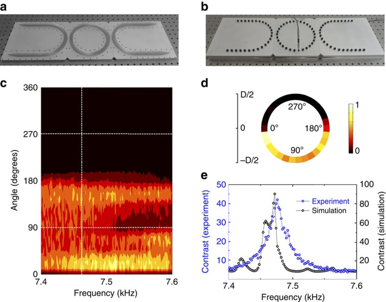
Figure 3. Coupling in the U-Ring-U shape waveguide complex.
(a) Photograph of the U-Ring-U shape metamaterial waveguide complex. The structure is a four-port system with two coupling connections marked by the red elliptical circles. (b) Illustration of the experimental measurement setup. The metamaterial waveguide is sealed in rigid rectangular pipes to eliminate radiation losses. A condenser microphone is inserted into perforated holes on the pipe wall, to measure the pressure amplitude in the metamaterial waveguides. (c) Measured pressure amplitude distributions in the coupling ring from 7.4 to 7.6 kHz. (d) The measured pressure amplitude distribution in the coupling ring at 7.46 kHz, replotted from the data on the vertical dashed line in c. (e) The measured and simulated pressure amplitude contrast at 90° and 270° positions in the coupling ring from 7.4 to 7.6 kHz, where the measured contrast is replotted from the data on the horizontal dashed lines in c.

