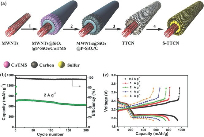
Figure 12.

a) Schematic illustration for the formation of S‐TTCN composite: 1) Uniform coating a solid SiO2 layer and a porous SiO2 layer embedded with C18TMS molecules on MWNTs; 2) formation of porous carbon nanotube by carbonization of C18TMS; 3) etching SiO2 layers to obtain tube‐in‐tube carbon nanostructure (TTCN) with MWNTs encapsulated within hollow porous carbon nanotube; 4) sulfur infused into TTCN to fabricate S‐TTCN composite. b) Long‐term cycling performance of S‐TTCN electrode at a high rate of 2 A g–1. c) Discharge‐charge profiles of S‐TTCN at various current densities from 0.5 A g–1 to 6 A g–1. Reproduced with permission.163
