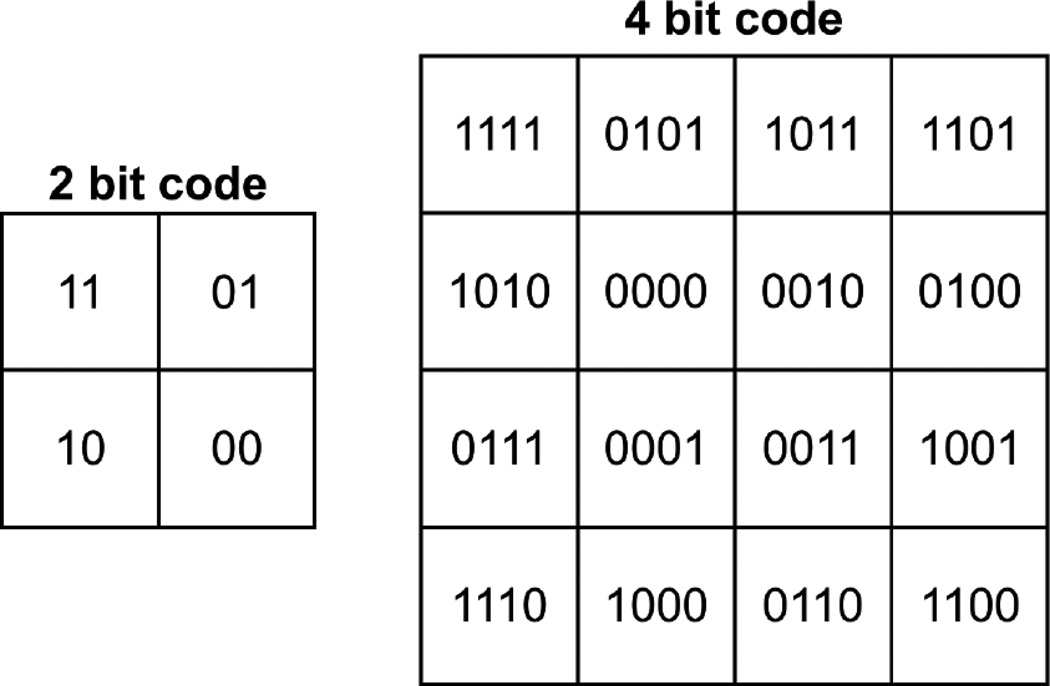
Figure 4.
Binary codes used for the 2 SiPMs in the 2 bit configuration (left) and 16 SiPMs in the 4 bit configuration (right) in this work. Each bit of the code corresponds to the connection of that SiPM’s split off channel to a position channel (1) or a dummy resistor (0). The schematic representation of the 2 bit code is also seen in Figure 1.

