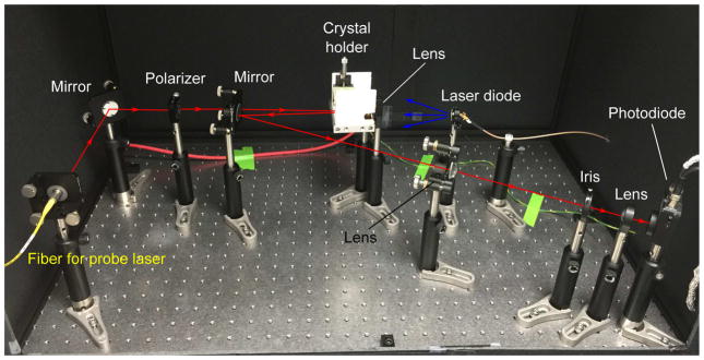
Figure 3.
Experimental layout of detection system. This layout is shown with laser diode radiation as an illustration. An isotope source can be placed beside the crystal holder instead of the laser diode (and associated focusing lens) to measure the isotope source radiation induced modulation signal.

