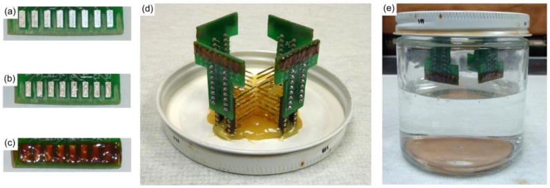
Figure 1. Soak test probe assembly and setup.

(a) Areas between and surrounding the bond pads have been roughened. (b) Silver epoxy on each bond pad for the carbon fibers. (c) Exposed bond pads with carbon fibers are covered with insulating epoxy. (d) Four PCBs with functionalized fibers are secured to the underside of the soak jar's lid. (e) Lids are secured to jars containing 1× PBS. Jars are then placed in a heated water bath.
