
Figure 5. Chronic implant impedances.
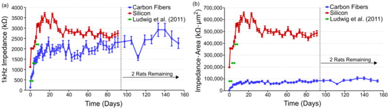
(a) Impedance values (mean ± standard error of the mean) for each probe type across time. Both electrode types saw an approximately 2 MΩ increase in impedance within the first two weeks. Values for the carbon fibers then leveled off while the silicon electrode values dropped before leveling off. Impedance values for 177 um2 silicon sites coated with PEDOT are shown in green [53]. The number of channels used for impedance analysis at each time point can be seen in figure S1. (b) Impedance values scaled by geometric surface area (mean ± standard error of the mean) for each probe type across time. Carbon fibers increased to approximately 80,000 kΩ·μm2 before leveling off, while the silicon electrode values peaked at about 650,000 kΩ·μm2 before steadying at approximately 500,000 kΩ·μm2. Similar to (a), values for 177 um2 silicon sites coated with PEDOT are shown in green [53].