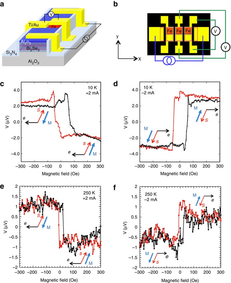
Figure 2. Device schematic and electrical detection of current-generated spin in TI.
Schematic (a) and top view (b) of contact layout with two parallel rows of collinear detector contacts, top row is ferromagnetic (Fe, red), bottom row is non-magnetic reference (Ti/Au). Magnetic field dependence of the voltage measured at the ferromagnetic detector contact with the magnetization collinear with the induced TI spin for bias currents of +2 mA (c) and −2 mA (d). Similar measurements at 250 K at +2 mA (e) and −2 mA (f).

