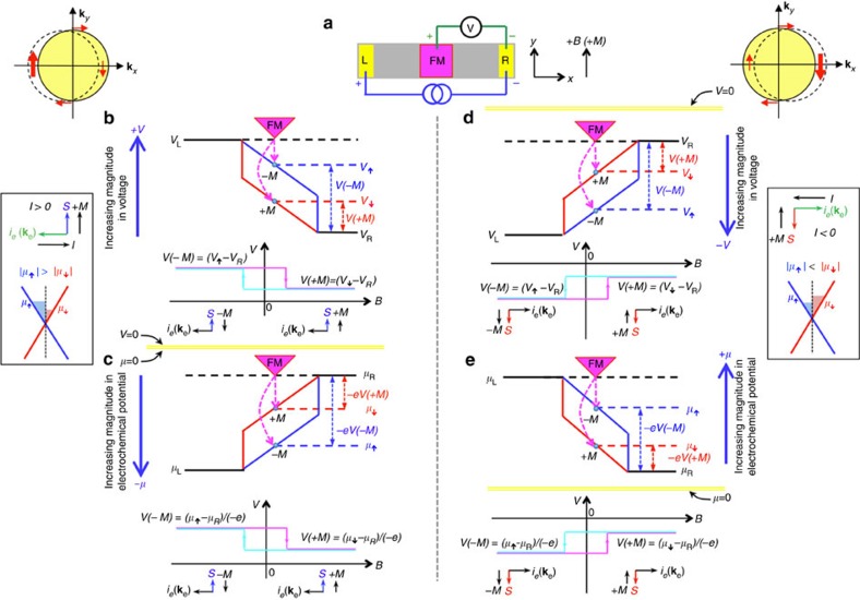
Figure 5. Model to derive sign of spin signal expected in TI.
(a) Schematic of a simplified 3-terminal device with a left (L) and right (R) electrode and central magnetic detector contact (FM), as well as definitions of voltage (V) terminals, magnetic field (B) and magnetization (M) directions. Model of the spin potentiometric measurement probing the current-induced spin polarization due to TI surface states, based on the spin-dependent electrochemical potentials: for positive bias currents using voltage profiles (b) and electrochemical potential (μ) profiles (c), and for negative bias currents in the form of voltage profiles (d) and electrochemical potential profiles (e). The definitions of current, spin (S), and magnetization directions are indicated for positive currents next to b,c, and for negative currents next to d,e. The blue and red solid lines indicate profiles for the spin-up (↑) and spin-down (↓) electrons, respectively. The blue and red horizontal dashed lines indicate the levels been probed by corresponding magnetization directions. For example, for b,c, the spin-up (blue) voltage and electrochemical potentials are probed by the FM detector with –M magnetization (oriented along −y), which has its majority spin oriented along +y (due to the opposite alignment of majority spin to its magnetization in magnetic metals47). The yellow horizontal lines indicate the zero axis for the voltage and electrochemical potential (V=μ=0), which is shared for b,c, and individually marked for d,e.

