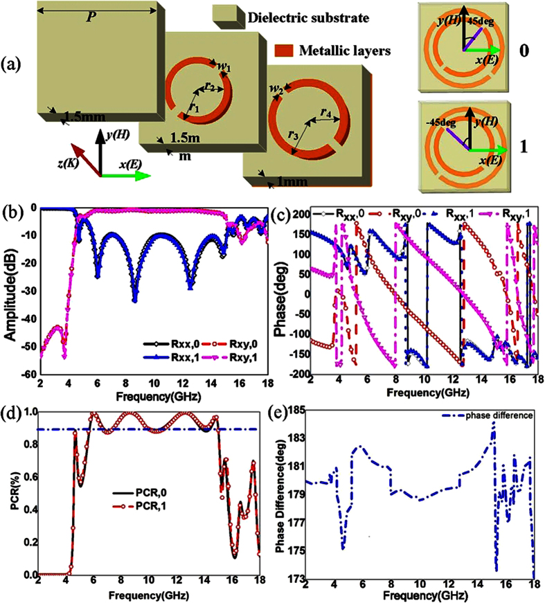
Figure 1. Geometry of the reflective convertor elements “0” and “1” and their reflective parameters.
(a) Geometrical parameters of the convertor. The dimensions of the convertor are P = 10 mm, r1 = 3.42 mm, r3 = 4.6 mm, r2 = 2.92 mm, r4 = 4.1 mm and w1 = w2 = 0.5 mm. Elements “0” and “1” are respectively the convertors with angles of 45 deg and −45 deg. (b) Amplitude of reflective coefficients for elements “0” and “1” with co-polarization (xx) and cross-polarization (xy). (c) Phase of reflective coefficients versus frequency. (d) Polarization conversion ratio (PCR) of the elements “0” and “1”. (e) Phase difference between the element “0” and element “1”.

