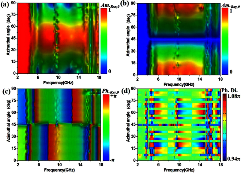
Figure 2. Simulated results of reflective parameters for convertor with different azimuthal angles from 2 GHz to 18 GHz.
(a) Amplitude of reflective coefficients for element “0” with co-polarization (Am.Rxx,0). (b) Amplitude of reflective coefficients for element “0” with cross-polarization (Am.Rxy,0). (c) Angle of reflective coefficients for element “0” with cross-polarization (Ph.Rxy,0) (d) Phase difference between the element “0” and element “1” with the azimuthal angle shifted from 0 deg to 90 deg.

