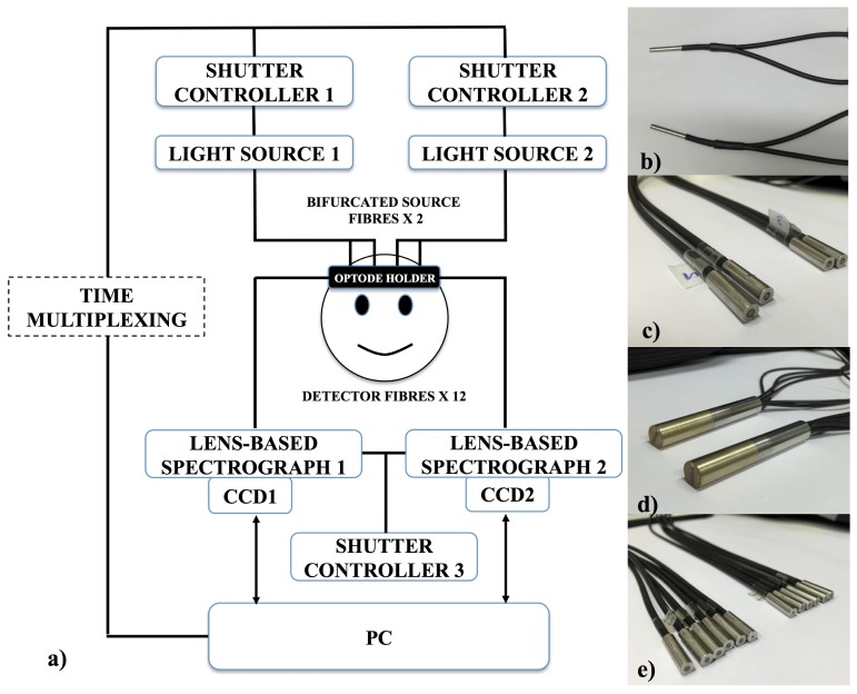
Fig. 1.
(a) Schematic showing all the components of the system. The system has two light sources, each has a solenoid shutter that is controlled by an electronic shutter controller with a time multiplexing mechanism. Light from the sources (filtered to 504nm – 1068nm) is directed to the subject by means of bifurcated optical fibre bundles, creating four source fibre bundles at the subject end. The diffused light from the subject head is collected using 12 detector fibre bundles branched from two fibre bundles, each of the two is connected to a spectrograph and a CCD camera. Both spectrographs are controlled by another electronic shutter controller. The system is run by LabVIEW software from a computer. (b) The common ends (attached to the light sources) of two bifurcated source fibre bundles. Bifurcation creates four individual source fibre bundles (c) at the subject end from two common bundles. (d) The detector fibre bundles at the spectrograph end. (e) The twelve individual detector fibre bundles which are branched from (d) and are attached to the subject.

