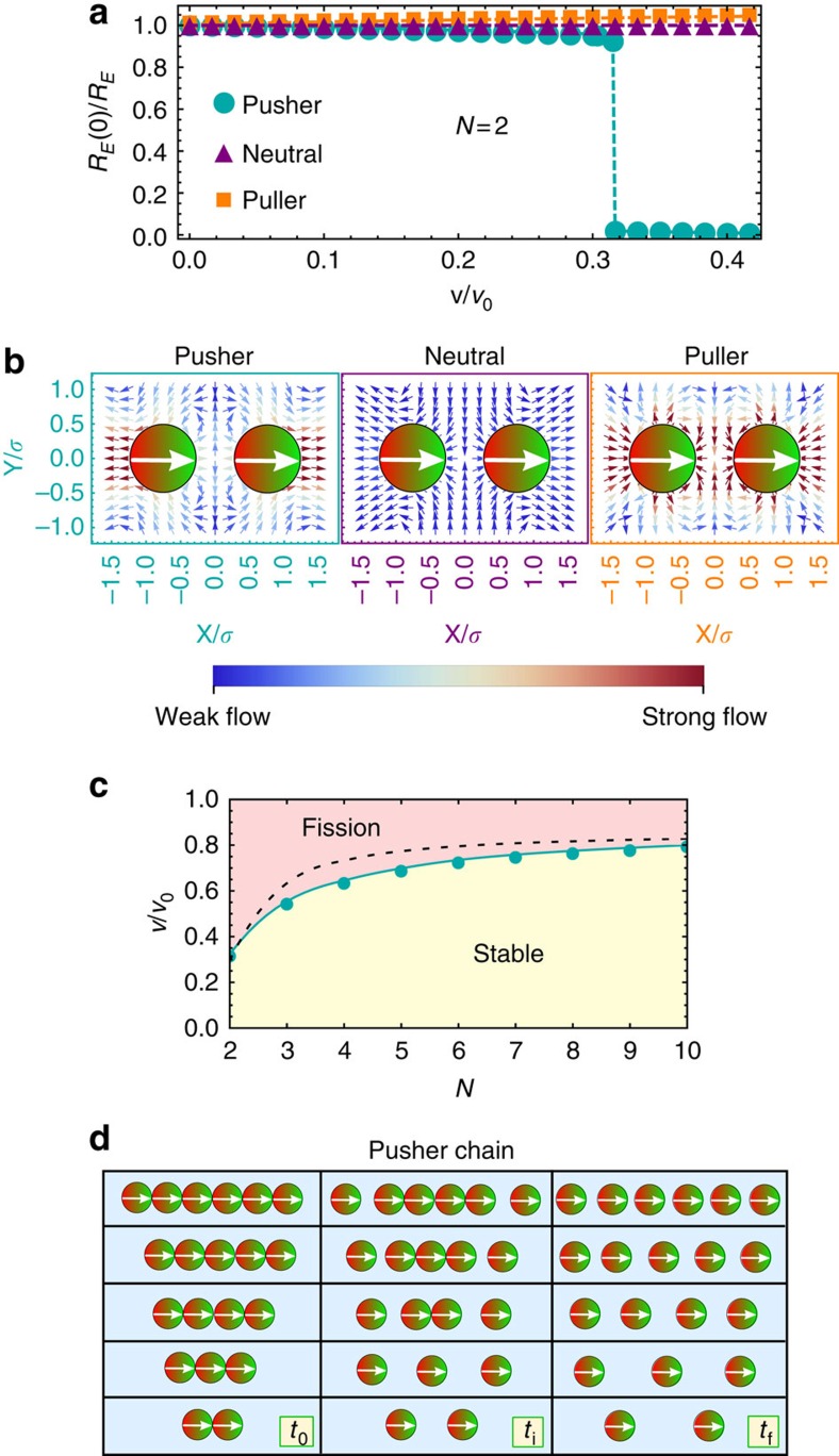
Figure 1. Stability of microswimmer chains.
(a) Relative end-to-end distance RE for all three HI cases and varied velocity v for fixed N=2. (b) Flow fields for a chain of N=2 magnetic microswimmers for (left) pushers, (middle) neutral swimmers and (right) pullers. The magnitude of the flow is indicated by the colour coding of the arrows, weak flow is indicated by dark blue and strong flow by dark red arrows. (c) Emerging state diagram spanned by reduced velocity v/v0 and number N of particles within a chain of pushers marking two distinct regions; stable chains for small and fission for large self-propulsion velocities. Numerical results (cyan line) obtained for soft sphere dipoles are compared with those for hard sphere dipoles (black dashed line). (d) Time series indicating the fission process for the cases N=2, …, 6, showing the initial configurations at time t0, the configuration after the first fission event at an intermediate time ti and the final steady state configuration of N individual particles at time tf, see also Supplementary Movies 1 and 2.

