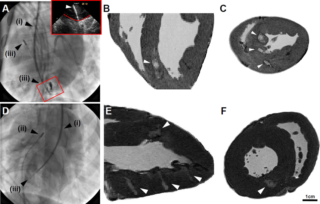
Figure 6.
Percutaneous Hydrogel Injection. A, Internal jugular approach toward RV injection, with alignment of the steerable introducer (i), intracardiac echocardiograph probe (ICE, ii), and deployment of needle assembly (iii). Inset: corresponding ICE view of deployed needle (indicated, white arrow) entering the myocardial wall (indicated, dashed red line). B-C, Long axis (B) and short axis (C) images of hydrogel injection (indicated, white arrows). D, Right carotid approach toward LV injection, including steerable introducer (i), ICE (ii), and deployment of needle assembly (iii) into the midwall of the LV. E-F, Long axis (E) and short axis (F) images of hydrogel (indicated, white arrows).

