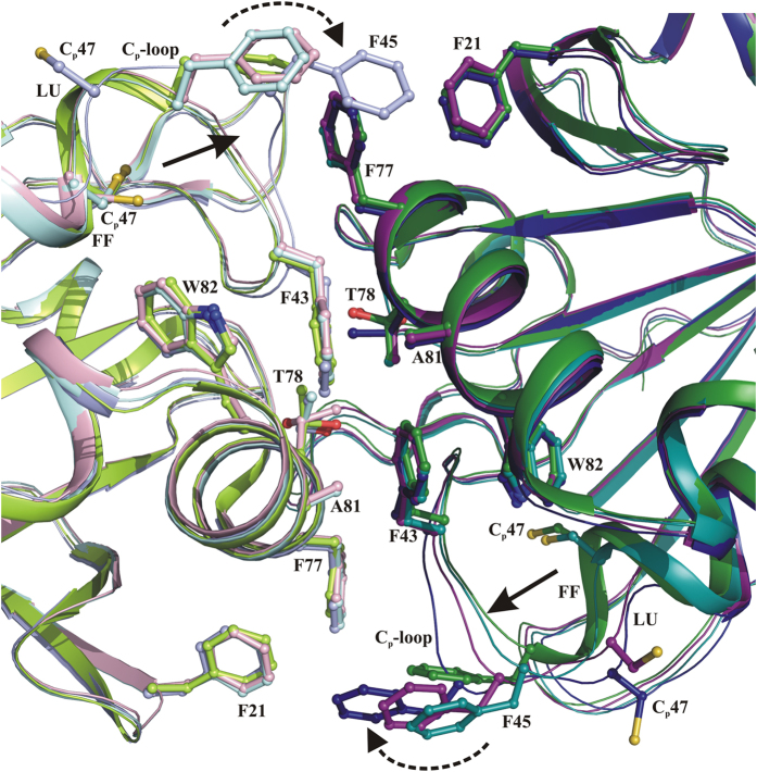
Figure 7. The oligomer interface region.
The decamer building interface region between two subunits are shown. The significant structural difference in the interface region is observed only in the residues that form the CP-loop. Compared with “FF” (green) CP-loop structure, the “FFlike” (blue), “LUlike” (magenta) and “LU” (cyan) is shifted away (solid arrow) from the interface region and this facilitates the destabilization of the oligomeric interface through F43 and F45 (dotted arrow). The complementary interface region formed by the neighboring subunit is shown with light colors shade.

