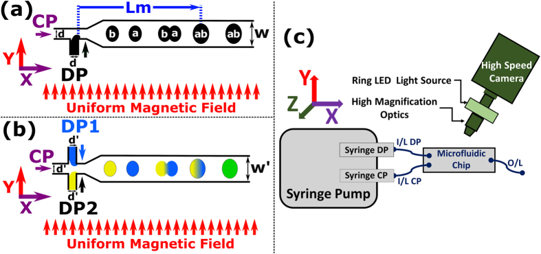
Figure 1.
Schematic of uniform magnetic field induced merging of (a) Ferrofluid droplets (150 μm channel height). Under the influence of uniform magnetic field H, droplet ‘a’ (with velocity Va) merges with droplet ‘b’ (with velocity Vb), yielding a droplet ‘ab’ (with velocity Vab). (b) Colour dye + magnetite (ferrofluid) composite droplets (100 μm channel height). (c) Schematic of micromagnetofluidic setup68,69 (i) microfluidic droplet generation along the CP flow in the x-direction, (ii) magnetic field, H along y-direction (iii) high-speed imaging. The high-speed camera is mounted in the z-direction, perpendicular to both the CP flow and magnetic field direction. Inlet and outlet of the microfluidic chip are denoted by I/L and O/L, respectively. CP = continuous phase, DP = Dispersed Phase, d = 150 μm, W = 500 μm, d’ = 100 μm and W’ = 300 μm (not to scale). Please see Table 1 for ferrofluid properties.

