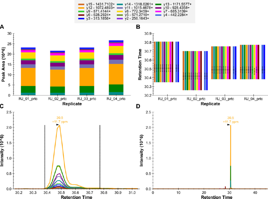
Figure 9. Skyline - QC Peptide GILFVGSGVSGGEEGAR++.
The total fragment ion signal (integrated over time) for the peptide GILFVGSGVSGGEEGAR++ is plotted as a bar for each of four QC replicate injections (A). The contribution from each individual fragment ion is displayed as a different color in the bars. The retention time of the peptide is plotted for each of the four replicate injections as a group of vertical bars (B). Within each group, there are colored bars, one for each transition measured for the peptide. Each bar starts and stops at the integration boundaries (in retention time) of the detected chromatographic peak. The retention time at the peak, and full-width at half max (FWHM) for each transition peak are overlaid on each transition as a horizontal and vertical black line, respectively. The extracted signal for the peptide from a single replicate is plotted in C and D at different levels of zoom, with the mass measurement error and retention time of the most intense transition annotated above the peak. The vertical lines on either side of the peak in C indicate the integration boundaries for the peak.

