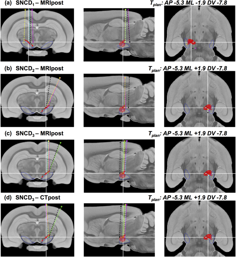
Figure 7. Reconstructed electrode trajectories for target SNCD.
(a–d) Three orthogonal cross-sections of the MRH template at the planned surgical target SNCD with the reconstructed trajectories for all animals of group (a) SNCD1 (animals A1-4) – MRI only, (b) SNCD2 (animals A2-4) – MRI only, (c) SNCD3 (animals A16-20) - MRI and (d) SNCD3 (animals A16-20) - CT. In panel (a), the electrode tip locations for animals A2 (magenta), A3 (yellow) and A4 (black) all fall outside the target region, with two cases (animal A2 and A4) showing more than 2° anterior-posterior inclination. Panel (b) shows all animals of group SNCD2 (animal A2: magenta, A3: yellow, A4: black), where electrodes were planned at a medio-lateral inclination of the trajectory of 21°. Only the electrode tip location in animal A3 (yellow) falls within the target region, while the two others are more posterior. Panel (c) and (d) show the electrode trajectories for animals of Exp.2 (i.e. SNCD3 (A16-20)) as reconstructed from post-operative CT and MR images. All electrode tips in Exp.2 were within the intended target region of SNCD3. Both MRI and CT-based observations of electrode tip positions show mutual agreement, but a subtle ML difference could be noted at the entry point for some trajectories.

