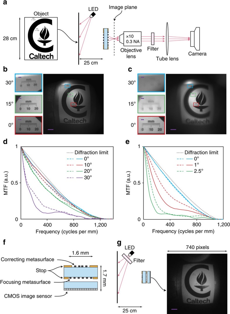
Figure 4. Imaging with the metasurface doublet lens.
(a) Schematic of the measurement setup. A pattern printed on a letter-size paper is used as the object. The image formed by the metasurface camera is magnified by the combination of the objective lens and the tube lens and is captured by the camera. A bandpass filter (centre wavelength: 850 nm, FWHM bandwidth: 10 nm) is placed between the objective and tube lens to reduce chromatic aberrations. (b) Image taken with the metasurface doublet lens and (c) with the spherical-aberration-free metasurface singlet lens. Scale bar, 100 μm. The insets show zoomed-in views of the images at the locations indicated by the rectangles with the same outline colours which correspond to viewing angles of 0°, 15° and 30°. Scale bar, 10 μm. (d,e) Modulation transfer function (MTF) of the metasurface doublet and singlet lenses, respectively. The solid and dashed lines show the MTF in the tangential plane (along x in Fig. 3b) and sagittal plane (along y in Fig. 3b), respectively. The diffraction limited MTF of a lens with aperture diameter of 800 μm and focal length of 717 μm is also shown for comparison. (f) Schematic drawing of a miniature planar camera realized using a metasurface doublet lens and a CMOS image sensor. (g) Imaging setup and the image captured by the miniature camera. Scale bar, 100 μm. The bandpass filter (centre wavelength: 850 nm, FWHM bandwidth: 10 nm) placed in front of the LED reduces the chromatic aberration.

