
Figure 3.
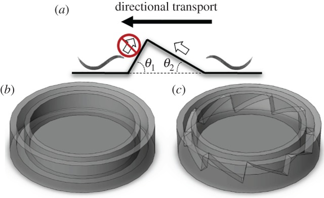
A schematic depiction of the control torus and the ratchet torus. (a) Side view of the saw tooth-shaped barrier. (b) The control torus with a flat floor. (c) Microratchet torus with ramps similar to the one shown in (a) patterned along its floor. (Online version in colour.)