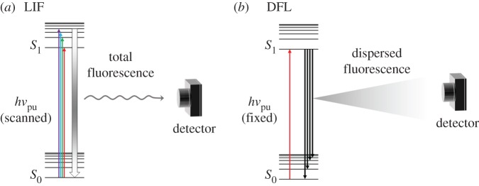
Figure 5.
Schematic of LIF (a) and DFL (b). In LIF, hνpu is scanned so that when it is resonant with a certain vibronic state, this state may radiatively decay to any vibrational level in the ground electronic state (S0, represented by thick gradient arrow). The fluorescence signal is then collected by a photomultiplier. In DFL, on the other hand, hνpu is set to a particular vibronic state, from which population may fluoresce to any accessible vibrational level of the S0 state. The total fluorescence signal is dispersed by a monochromator in order to deconvolute the information on the vibrational levels of the S0 state, and again collected by a photomultiplier. (Online version in colour.)

