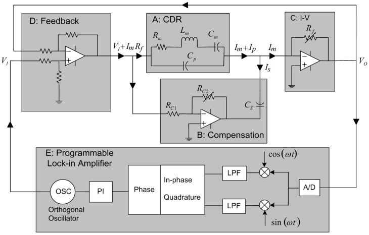
Figure 2.
(Sub-circuit A): The equivalent circuit model of the CDR; (Sub-circuit B): Circuit used to compensate for the parasitic capacitance present; (Sub-circuit C): Current to voltage converter, nominal value of Rf is 100 Ω; (Sub-circuit D): A current feedback scheme is used to increase the Q of the system; (Sub-circuit E): A digital lock-in amplifier arrangement (Zurich HF2) is used to track the resonant frequency.

