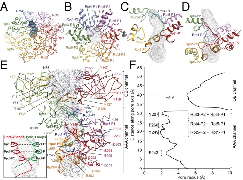
Fig. 4.
Architecture of the substrate-translocation channel. (A) Overview of the AAA channel calculated by the HOLE program (50). The channel is rendered by surface dots. The dashed green curve indicates the spiral shape formed by the pore-1 loops. (B) Top view of the pore loops aligning along the channel axis from the perspective of the OB domain. (C) Close-up side views of the pore-1 loops from six Rpt subunits decorating the channel, which align along the channel in a spiral staircase formed from Rpt1 to Rpt5, with a backward recession in the Rpt6 pore-1 loop that is slightly away from the major channel pathway. The pore-1 loops form a helical part of the channel interior as illustrated by the dashed green line. (D) Close-up side view of the pore-2 loops from six Rpt subunits decorating the channel, which form a complete spiral staircase from Rpt1 to Rpt6. These pore-2 loops form another helical part of the channel interior, illustrated by the red dashed line. (E) Side view of the complete ATPase channel, including components from both the OB and AAA domains, calculated by the HOLE program (50). Side-chain patterns observed along the substrate-translocation pathway are highlighted. The five tyrosine residues, highlighted by transparent sphere representation, and a number of hydrophobic and negatively charged residues decorate the AAA channel; color codes for ATPase protomers match those shown in A. (Inset) A schematic cartoon showing that the pore-2 loops of Rpt3, Rpt4, and Rpt5 pair laterally with the pore-1 loops of Rpt4, Rpt5, and Rpt1, respectively, to form the three narrowest constrictions in the AAA channel. (F) The channel radius along the pore axis approximately estimated by HOLE (50), showing the three narrowest constrictions in the AAA channel but only one narrow constriction in the OB channel that is more than twice as wide as those of the AAA channel.

