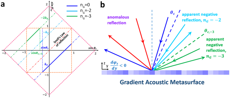
Figure 2. Schematic demonstration of the general case of the apparent negative reflection with the gradient acoustic metasurface.
(a) Relation between sin θi and sin θre. The blue, cyan and green solid line correspond to nG takes the value of 0, −2 and −3 respectively, which represent the intrinsic anomalous reflection state  and the another two allowed apparent negative reflection states
  and
and  correspondingly. The red dotted line represents the specular reflection state
  , which is forbidden here. The orange dotted square circles the domain of all possible reflection states and the pink dotted square defines the all allowed phase gradient shift that maintains the anomalous wavefront manipulation characteristic of the gradient metasurface, when the amplitude of the surface phase gradient is greater than 2k0, the structured gradient metasurface works as a uniform flat impedance ground. (b) Schematic illustration of the anomalous reflection (red and blue solid beam), the apparent negative reflection taking place beyond the critical angle
  when nG = −2(cyan solid beam) and nG = −3(green solid beam).

