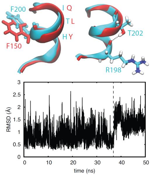
Figure 6.
The hydrogen bond between T202 and R198 stabilizes a bend in the axis of the α-helix. Top: Structures of the C-terminal zinc finger of TTP (red) and TIS11d (cyan). The orientations of the side chain of F150 (TTP, red) and F200 (TIS11d, cyan) are shown on the left. The hydrogen bond between and OR198, depicted as black dashed line, is shown on the right. Oxygen atoms are depicted in red, nitrogen in blue and hydrogen in white. Bottom: The root-mean-square deviation of the backbone of the α-helix in TTP (residues 147 to 153) is shown as a function of time. The dashed line indicates the change in the α-helix conformation that causes a displacement of the F150 side chain to a position where it does not stack against H166. Data are shown for the first half of the unfolding MD trajectory of TTP (100 ns in total)

