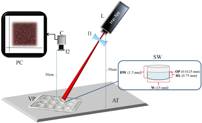
Fig 1. Schematic diagram of the speckle experimental setup.
Experimental setup, with data of the setup and the VDRL well, L laser; C CCD camera; PC computer; l1 lens of the laser; l2 lens of the camera; AT anti-vibration table; VP VDRL plate; SW sample well; OP object’s plane; W width; HL height of the liquid; HW height of the well. The diagram is not drawn to scale.

