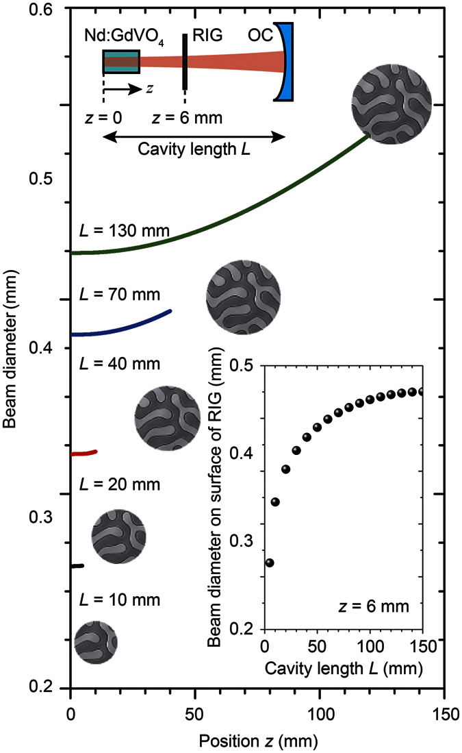
Figure 2. Beam diameter in the cavity with respect to the cavity length.

Lasing material Nd:GdVO4, RIG, and OC were placed in alignment as shown in the schematic on the upper left. The RIG was placed 6 mm from the Nd:GdVO4 surface (z = 6). The beam spot sizes at the surface of RIG with various cavity lengths are expressed by the circular images of MMDs, and the diameter is plotted in the bottom right inset.
