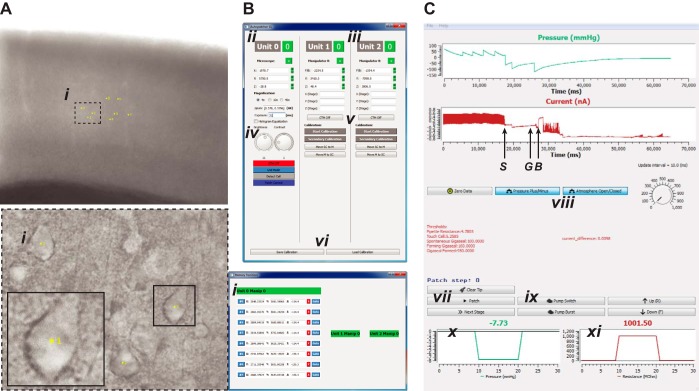
Fig. 3.
GUIs of the Python-based software featuring image acquisition, manipulator, and patch control. A: camera view of a brain slice with target cells (i) selected at a low magnification of ×4 (top) and at a high magnification of ×40 (bottom left). Yellow labels indicate the cell no.; coordinates of the cells are stored as the corresponding sequence of memory positions and indicated in the GUI (bottom right) B: main GUI providing settings for image acquisition, microscope stage, and micromanipulator control. ii, Microscope stage: controls include settings for stage coordinates, magnification, pixel-μm calibration; iii, micromanipulators: user can initiate automatic calibration and control individual micromanipulators; additional micromanipulator units are automatically recognized and added; iv, controls for camera exposure (in ms), image brightness, and contrast; v, automatic pipette calibration; vi, calibration save and load. C: patch control GUI during an ongoing patching experiment. Top trace indicates pressure (in mmHg); bottom trace indicates current measurements from the patch amplifier (letters denote key events in the patch-clamping process: S denotes the touch cell surface event, G denotes the time point at which a gigaseal is obtained, and B denotes when break-in is achieved). vii, Automatic patch algorithm; viii, independent valve configuration control: allows user to override the patch algorithm and manually apply user-required positive or suction pressure; ix, independent pump control: allows user to override the patch algorithm and control the pump; x, real-time pressure; xi, real-time resistance.

