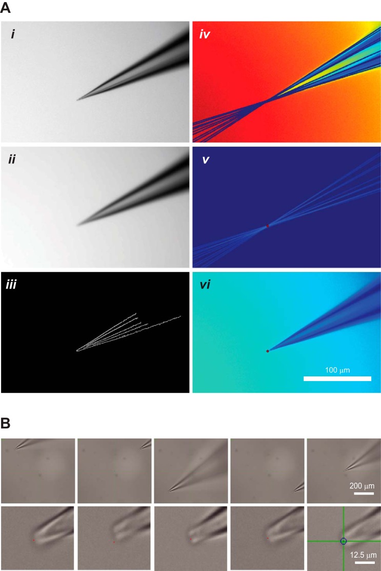
Fig. 5.
Computer vision-aided identification of the pipette tip coordinates. A: image acquisition and pipette tip detection. i, Original pipette image acquired by the microscope; ii, image after application of Gaussian blur; iii, Canny edge detection algorithm applied to the image in ii defines the contours of the pipette tip; iv, Hough transform performs feature extraction to fit the pipette contours with lines; v, color inversion and intensity calculation are used to detect the lines' point of intersection; vi, pipette tip detected by the algorithm as indicated by red dot. B: automatic pipette calibration achieves high precision. To test the precision of automatic pipette calibration, a predefined calibration grid was used and the pipette tip was then targeted to the centroids of four quadrants and the screen center. Top row shows the relative location of the pipette on the screen at ×4 magnification; bottom row shows the precision of the pipette placement at ×40 magnification. Red dots are 1 pixel in size and are the target locations.

